Hardware NES Emulator Part 1: Video Output
*This is the first part of a series where I detail what makes up a game console emulator. The first few parts will cover the video and the GPU logic that allows you to draw to the screen, this encompasses the scope of what was probably the most enjoyable project I did during my undergrad. The report for which can be seen here.
The first step in my opinion of making any video game console is deciding how to draw to the screen. When I set out to make an NES on an FPGA, I was immediately overwhelmed before I even wrote a single line of SystemVerilog.
This is because working on hardware allows you an almost exhilirating amount of flexibility when it comes to making your choices. HDMI? VGA? Composite? any kind of video output format you want, we can do it. Let's look at some of the most popular options available on most devices.
Let's say you have a frame buffer that contains RGB color values for each pixel on a physical screen. Lets see how Composite, HDMI, and VGA would draw this frame buffer to the screen.
Composite video
Here's what the composite video looks like for a single line of grayscale data.
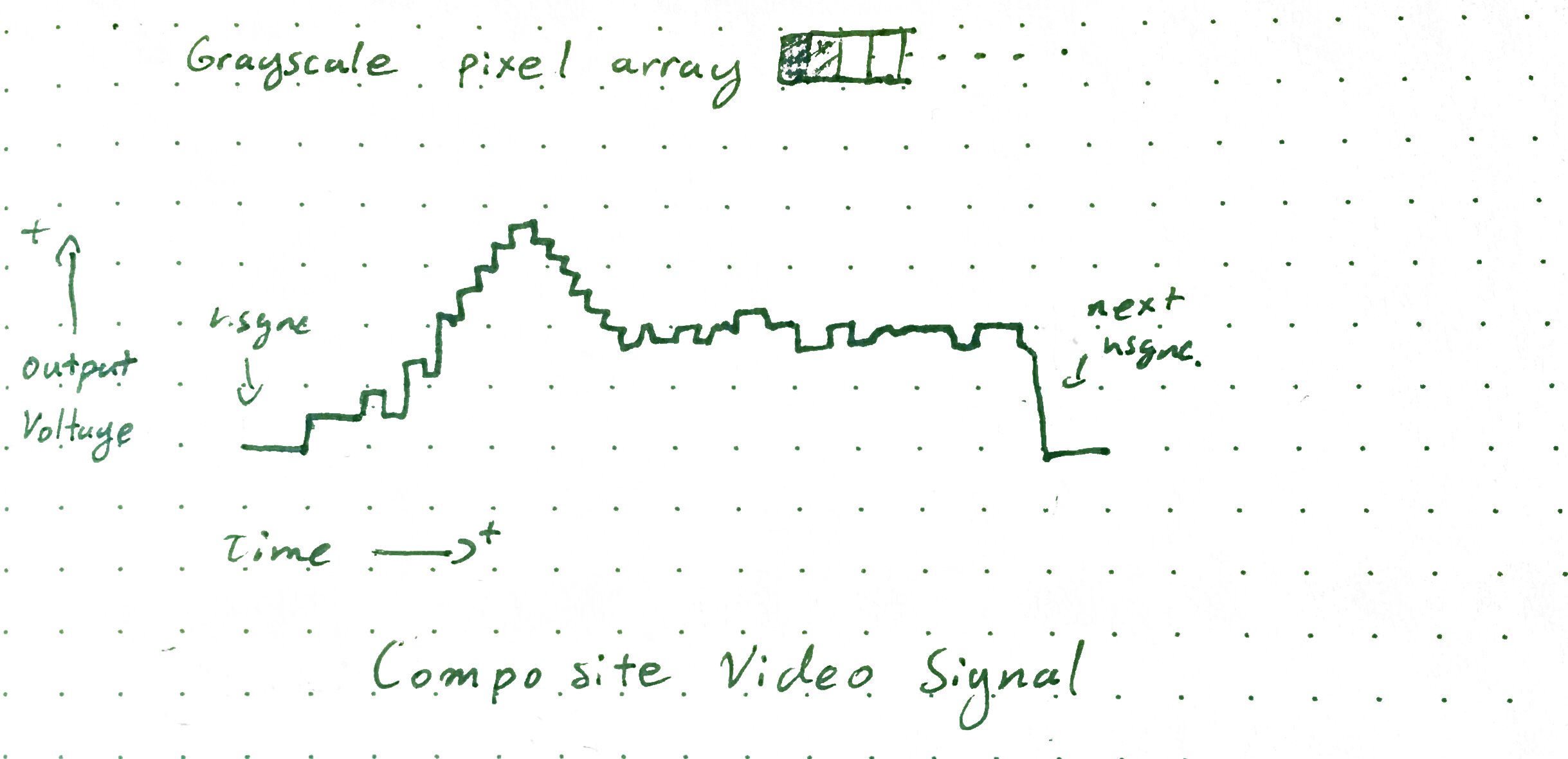
On each scanline the voltage gets pulled very low to the 'blanking level'. This signifies the start of each horizontal blank, after this blank occurs a small period of setup happens. During this time the colourburst is sent as well as the level for 'black' is established. Then after this, the device starts tracing the input data with intensity values proportional to the input voltage. Higher the voltage, the brighter the trace is at that instant in time.
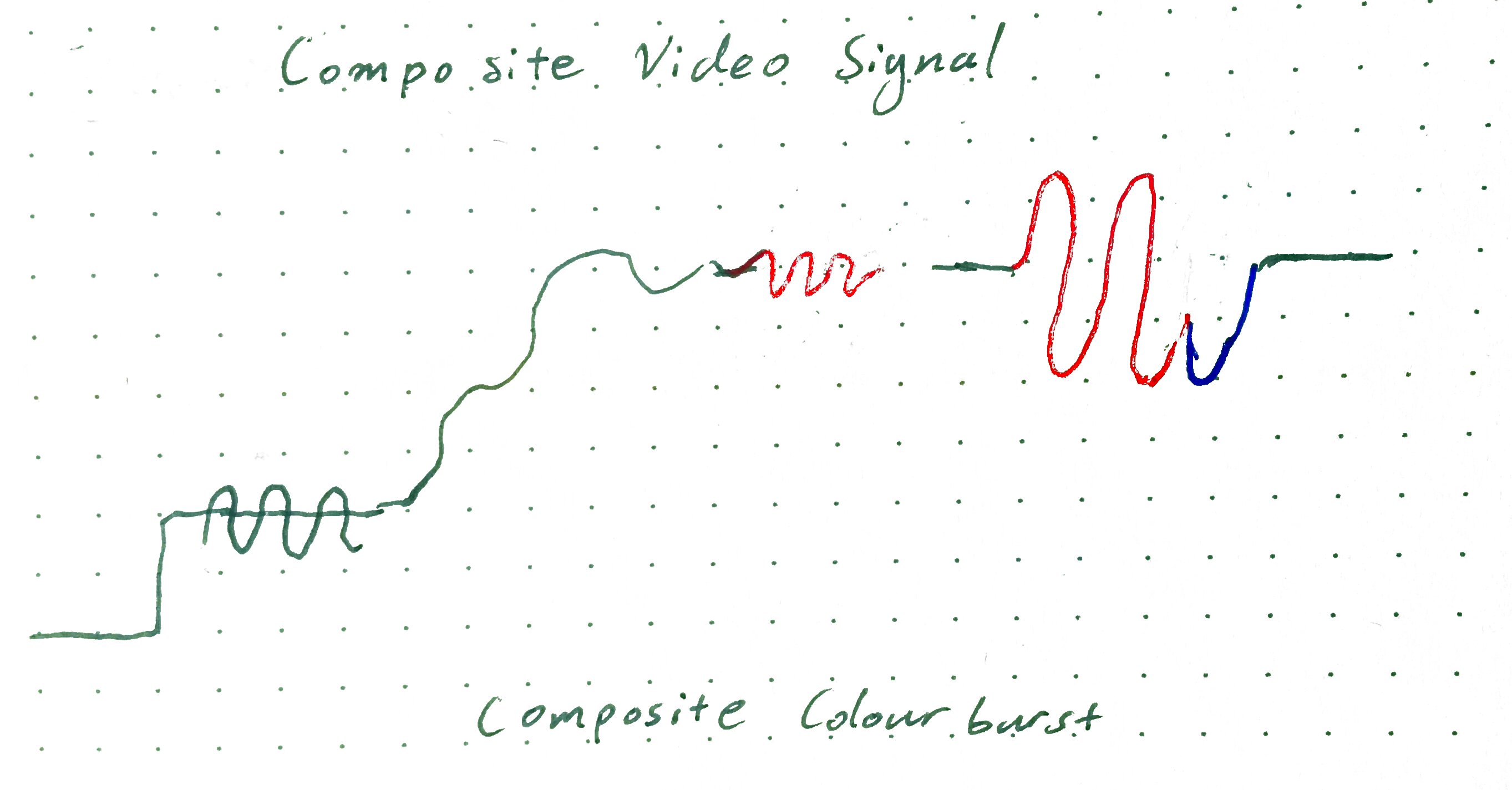
When color is added in the gravy thickens quite a bit. A color burst happens during the setup time period. This causes the recieving device to synchronize a sinewave to the colorburst's phase. Then when the actual tracing begins to happen, a hue/saturation signal the form of an amplitude/phase modulated signal appears superimposed on the grayscale signal. The phase determines the hue while the amplitude determines the saturation.
In a nutshell Composite video's workflow is:
- serialize each row of your array and sweep each individual value in that row.
- Intensity is transformed into an analog waveform of varying intensity, corresponding to each pixel's value
- This sweep happens on each line and this is called a scanline.
- A colorburst signal is sent at the beginning of each line and acts as a reference for a later modulated chroma signal on the line, with different phase lags signifying color channels.
- there's also some horizontal blanking and vertical blanking that is inserted for the purposes of synchronization.
This tech was originally designed to transform tv signals that flew over the air and into an antenna. From an era where analog electronics were so much faster than digital, so that's why it may feel a bit unintuitive especially for somebody like me who feels much more at home in the world of computers and digital logic. So it makes sense that it's a pretty complicated signal electrically. To properly create a composite adapter we would need
- Digital to phase modulation for the Hue
- Digital to amplitude modulation for the Saturation
- DAC for the Intensity
- Oh and convert our RGB domain colors into HSI
There are ways to create simple versions of each thing. For example the colorburst signal can be done via some ghetto DDS through a filtered squarewave generated by a constant, clock-fed counter. It's amplitude can then be adjusted in a number of ways. Resistor ladder into a transistor gate, Op-amp with a digital potentiometer. Maybe even a DAC with a Digital Modulator, the sky's the limit here.
So while do-able, it is still quite complicated and would definitely add a couple of days to the project.
HDMI
What about HDMI? Well, despite being both modern and fully digital and has a boatload of features its' general workflow is actually surprisingly simple. (If we choose to ignore the frills that are available)
- Convert each channel into 8 bit color (if they are not in 8 bit already)
- Encode each 8 bit color value into 10 bit TDMS format
- Juice up your pixel clock by 10x and shift out each 10 bit encoded color value for each pixel on the screen.
- Pulse the per pixel clock
- Repeat until the scanline is completed, add blank time for hsync and repeat for each other scanline
- add blanking time for vsync and wait out till the next frame draw
It's got a pretty snazzy physical interface too. It doesn't require nearly as much circuitry
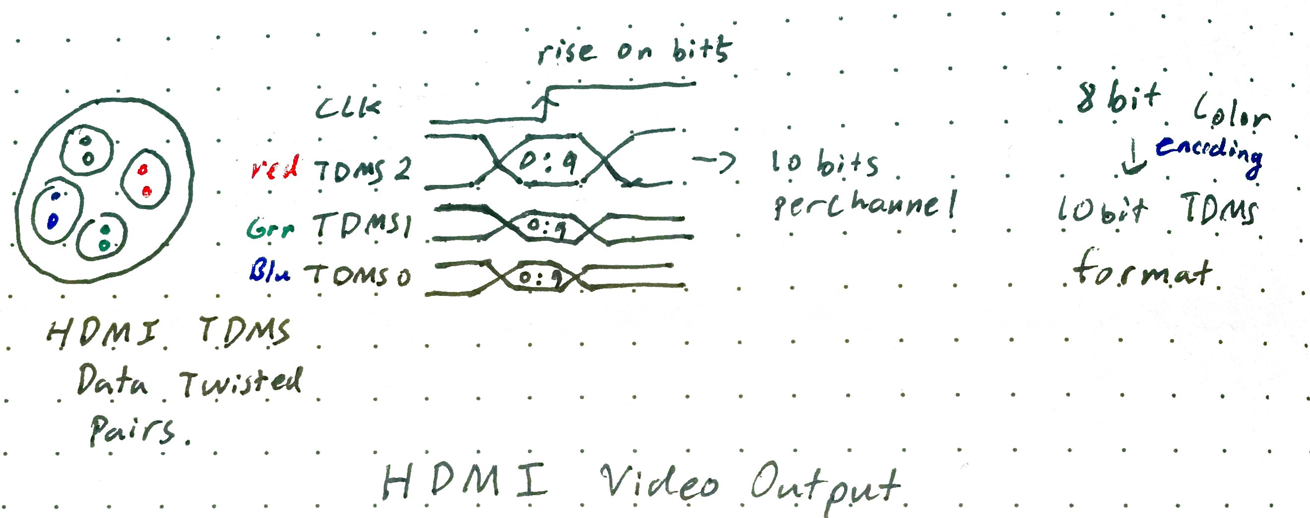
It's literally 4 differentially paired digital lines. All you would have to do is find some kind of breakout for it (adafruit sells them pretty cheap.) But my only problem with it is... I actually don't have any computer monitors at the lab which can take HDMI. But I do have a ton of old VGA monitors! Also some VGA headers from a previous project. So let's look at VGA as well.
VGA
Alright VGA is kind of a hybrid between the two. (Kinda makes sense considering it is most popular in the time directly proceeding one and shortly before the other one.) It's 3 channels of analog output but the time steps can be thought of as discrete and digital.
The workflow for VGA shakes out like this:
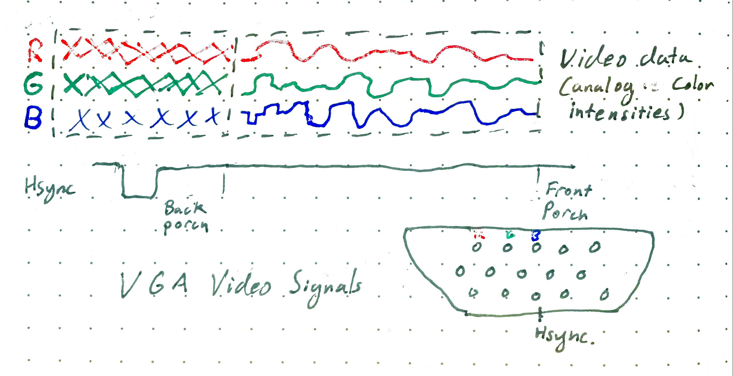
- For each row in your buffer, scan across each row.
- For each discrete value in each row output an analog voltage onto each of the color channels.
- Add time for hsync and vsync
This is great for pretty much the same reasons why HDMI is great: no complicated circuitry or wizardry required. However it has the added benefit of having a lower data rate and actually works with the crappy monitors I didn't mind bringing into the lab? Yes please! There's only one hiccup here though that little point about outputting an analog voltage onto each row.
Well this is where we can take advantage of some of the properties of the video we are outputting. The NES video
For example take a look at the NES's video. The colour pallete has a total available number of 64 colors. This means, that we don't actually need very good resolution. As you can see from my NES to 9 bit color conversion spreadsheet. 9 Bits of color (3 bits per colour channel) offers me some pretty darn accurate colors. This requires nothing more than just 3 bits of a resistor divider network. (the resistor values are available here.)
Furthermore VGA allows me to do some slightly nasty things such as smearing my scanlines and delaying my pixel outputs which would've been slightly more difficult to do in HDMI (more details on that in a different post).
Concluding the video output
But that doesn't mean VGA is the best choice, or even the right choice in the long run. HDMI is incredible in that it can output high definition video without much more hardware resources than a moderate clock. Unlike a VGA output, which would require a low speed DAC. While composite video is a much more true to form option as the original NES did indeed output composite video.
At the end of the day, the goal is to get video onto a screen. For this project It didnt really matter how. So the goal is to whatever makes sense given the situation. In my case here, both HDMI and VGA are excellent choices. They are both digital, widely used, flexible and compatible with most devices out there. Disregarding frame buffers, they are both also quite cheap in terms of logical elements on an FPGA. In fact it's easy to see why many commercial products just go ahead and offer both of them.